| In this tutorial, you will learn
how 3d models work for Battlefield: 1942 and Battlefield: Vietnam
3-D models (also know as meshes) for Battlefield:
1942 and Battlefield: Vietnam are stored in the StandardMesh.rfa archive
file.
Requirements:
- Discreet® 3ds max® 5 or higher, or Discreet® Gmax®
1.2 or higher
This is not so much a tutorial as it is an explanation
of the different components contained in a StandardMesh file, when to
use them, and how to optimize them to maximize gameplay.
This explanation is best used in conjunction with
"Tutorial 5 - Overview of the BF1942 Damage System" found
in the "Step by Step Scripting Tutorials" section. The overview
describes how the damage and collision system works and how to assign
materials, while this tutorial describes how to create and optimize
those pieces. If you haven't done so yet, take a moment and look through
the Damage System tutorial. It's not necessary that you understand and
remember all the information in it right now, but you should try to
become familiar with how the system basically works.
Visible LOD's:
Let's say we want to model a new vehicle. A good
workflow is normally to model the highest resolution first and then
base all other parts off of it. For this tutorial I made up a hovering,
rocket-powered tank. I chose this example because it has lots of pieces
to be optimized. Here is the highest LOD version. That is, the version
with all the curved surfaces and extra bits and pieces:
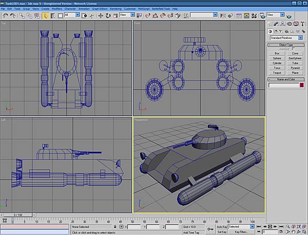
This version of the model will triangulate to around
3,000 polygons. This may sound like a lot, but thanks to LOD's this
really isn't a problem for the game engine. "LOD" stands for
"Level of Detail". What this means is that there are actually
several different versions of the model that vary in polygon count from
the main LOD (the one you see here) all the way down to a version that
is extremely simple. The reason for this is that once you set up the
geometry.con file (see the other tutorials), the engine will automatically
switch to increasingly simpler versions of the model as you move away
from it.
Say there are 5 of these tanks on the screen scattered
at varying distances from the player. What this means is that if the
player is standing right next to one of them, the game engine will select
the most complex version and render it. For the other tanks in the background,
the game engine will select the appropriate simplified version so that
it doesn't have to render as many polygons.
The theory is that the farther away you are from
something, the less detail you will be able to make out. In other words,
there is no sense for the game engine to try and render several thousand
polygons for a vehicle that is way out on the horizon and will only
take up a few pixels on your screen anyway.
How do we make those additional LOD's? Well, there
are two ways. The first is to actually model each individual LOD, removing
detail and simplying things like round edges more and more for each
version.
Fortunately, there is an easier way. You can simply
use the "Auto Generate LOD's" function in the Battlefield
Tools Exporter. If you want to try this yourself, do the following:
(Note: Auto LOD generation only works in 3ds Max, not Gmax.)
- Launch 3ds Max and create a model. It can be
anything, just be sure to put lot of detail on it. If you make several
pieces, make sure you combine them all into one so that you only have
one mesh.
- Name this mesh "lod01"
- Select "Model Import/Export" from the
"Battlefield Tools" Menu in 3ds Max. You will see the following
window:
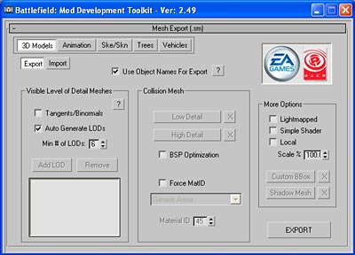
- Check the boxes next to "Auto Generate LOD's"
and "Use Object Names For Export". Leave "Min # of LOD's"
at 6 and all other options at the default. Click on "Export"
and give the file a name.
- Reset the scene so that it is blank and again
select "Model Import/Export".
- This time when the window opens, select "Import".
Set the options so that there is a check box next to "Visible"
and no checkbox next to "Only Main Vis LOD". Your options
should match the following:
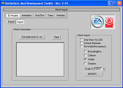
- Click "Import" and select the file
you just exported. You should now see all the LOD's that were created
automatically during export. Here is the scene with the tank LOD's.
I've spread them out so that you can see them all:
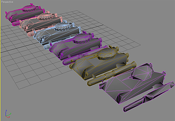
It's a bit hard to see, but the LOD01 (the original)
is in the back and LOD06 (the simplest version) is in the front with
the progressively simpler versions in between. Notice how bad LOD06
looks. This is actually okay because as I said, you will never see this
in the game except from very far away.
It's a good habit to generate LOD's for pretty
much all objects in the game. After you get familiar with how the system
works, you might want to try to make some of the custom LOD's yourself
for things like buildings and so on. Just leave the auto-generate settings
the same as the previous example and name any meshes you've created
as "lod01","lod02", and so on. There is no need
to make all levels if you don't want to. The exporter will automatically
fill in the missing levels.
Now back to our workflow...
The Collision Meshes:
We've now taken care of optimizing the visible
meshes for the rendering engine. If you've set up the script in the
geometry.con files to switch LOD's at the proper distances, you've done
pretty much all you can to reduce lag caused by rendering. (If you still
get render lag, you may want to make sure none of your models are excessively
high in poly count. import a few of the stock BF: 1942 models into Max
as examples.)
The other main cause of lag, especially in network
games, is collision detection. The simple explanation for this is that
basically, for every frame, the server has to keep track of every object
in the game to see if it's collided with any other object in the game.
This includes vehicles, buildings, projectiles, and even the ground
and water.
If you think about this for a second, you realise
this is no simple feat, even for the fastest server. This is the reason
for the "Damage System". It's a way of letting the computer
not have to keep track of every last polygon in the game, and what makes
it work are two things: the bounding box and the collision meshes.
Take for instance a projectile fired at our little
rocket tank. If you've glanced over the Damage System tutorial I mentioned
earlier, you may remember that as the shell approaches the tank, the
first thing the computer does is decide whether or not the shell is
inside the tank's bounding box. I'll talk more about creating the box
later. For now just imagine a 6-sided box around the whole tank. The
box is actually made up of 12 triangles. (Games all use triangles, not
squares, so six sides equals 12 triangles. Study the screenshot of the
tank LOD's above to see the triangles.) When the shell approaches the
tank, the computer looks at the shell and looks at the 12 triangles
of the box to decide if the shell is inside it or not. If the shell
is not inside this box, the computer completely ignores the rest of
the tank. Because of the bounding box, the computer has only had to
look at 12 triangles instead of the thousands that make up the tank
itself.
Suppose the computer has decided that the projectile
is inside the box. The very next thing the computer does is look
at what are called the "Collision" meshes, which we will set
up now.
Basically, a collision mesh is like an LOD, only
you don't generate it automatically because you want to make some decisions
about how to optimize it. There are two collision meshes used in the
game: Collision Mesh 1 and Collision Mesh 2. Each of these has a specific
function.
Collision Mesh 2:
The first one we are going to make is collision
mesh 2. This is the more complex of the two and is used primarily to
determine A: collisions between the object and projectiles, and B: collisions
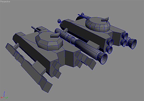
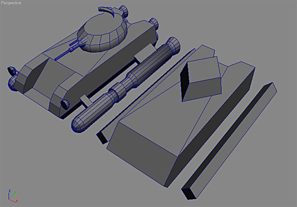
between the object and the player. Here is the Collision Mesh 2 that
I made for the Rocket Tank placed next to the original:
When you are creating your Collision Mesh 2 and
trying to decide where to optimize, picture a bullet approaching the
various surfaces of your model. You want to make the mesh as simple
as possible to reduce lag, but at the same time you need to keep it
accurate. How many times in Battlefield have you shot at something from
behind a tree or another object? you look at the aiming crosshair and
you have a clear shot, but you are really close to something like a
tree and when you fire, instead of hitting your target, you "hit"
the air next to the tree. This is an example of a collision mesh that
has been simplified too much. In case you haven't figured it out, collision
meshes are invisible, and in this case the collision mesh for the tree
doesn't "match up" with the outline of the visible tree.
Anyway, as I was saying, picture a bullet approaching
this tank. The first thing you want to decide is which details are actually
important. The battlefield is a fast-paced environment. Bullets whizz
by faster than you can see, and in the confusion of battle it's not
necessary to worry about every little collision. Take for instance the
headlights. The tank is probably moving, and the bullet is also moving.
The headlight is a pretty small object. Are you going to notice or care
if a bullet hits the headlight? probably not. Suppose the tank is sitting
still and you are using it for cover. Can you hide behind the headlight?
probably not. Is it big enough to provide "effective" cover?
Again, probably not. If you were standing behind that headlight in a
combat situation, it's just as likely that you would get hit just above
or below the headlight or that the bullet would pass straight through
it. It's up to you how "accurate" you want your meshes to
be, but every polygon you add to a collision mesh increases the time
it takes the server to evaluate that object. I decided to remove the
headlights from the collision mesh and saved 200 polygons. That's 200
less calculations that the server has to make for this tank.
That's mostly an example of a player using a "detail"
for cover. Instead let's say that it's a bazooka rocket or tank shell
that's about to hit that headlight. If a tank shell hit only
the headlight, would it destroy the tank? Not likely. This would be
another example of why you wouldn't need to include it in the collision
mesh. Now let's say that the incoming tank shell is coming in at a different
angle. This time if the headlight wasn't there to stop it, it would
slam into the body of the tank. Is the headlight needed in the calculations?
No. Since the shell is going to hit the tank anyway, why do the calculation
twice? Get the idea?
Now take a look at the engines on the sides of
the tank and the rocket nozzles on the back. Notice how smooth and round
they are on the "main" model? This looks nice, but takes an
aweful lot of polygons, 600 on each of those side engines to be exact.
Compare those to the engines on the collision mesh. The ones on the
collision mesh are basically just diamonds. Apply the thinking from
the headlight example. The engines need to be there. If you shot at
one of them, you would definitely expect to hit them or be able to hide
behind them. The player would feel cheated if they couldn't, but think
about the different paths that a bullet could take. Do the engines really
need to be "round"? As long as there is something to stop
the bullet, are you really going to notice the difference? Probably
not unless you look really hard. The same with the radar dish
on top of the turret. It is fairly detailed in the main model, but just
a triangle in the collision mesh. I've also removed the mounting post
from the collision model. It's just a few polygons, but they all add
up. Since it's such a small detail, there's no reason for it to be there
and will just slow down the computer that much more.
Lastly, it's hard to see, but I left the barrel
of the gun as a cube. If I was just worried about bullet collisions
I would probably have removed it entirely, but I can picture a player
climbing around on the tank, and they would expect to be stopped by
the barrel if they ran into it. It would bother me too much to be able
to just run right through it. This is an example of an "design"
decision rather than a practical one.
Collision Mesh 1:
Collision Mesh 1 is the other collision mesh, and
the thing to remember is that it deals exclusively with
collisions between vehicles and collisions between vehicles and structures
like buildings and trees. (There is some speculation that this may not
strictly be true, but it is as far as we are concerned.)
Here is a screenshot of Collision Mesh 1 and the
main model:
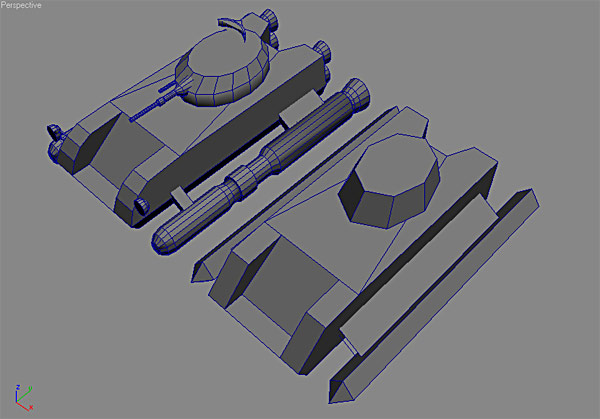
Notice how much simpler Collision Mesh 1 is than
even Collision Mesh 2. A good workflow tip is to create Collision Mesh
2 first because most of the time you can just simplify it even more
to make Collision Mesh 1 instead of having to start over from scratch.
The thing to keep in mind when optimizing Collision
Mesh 1 is that it only deals with collisions between vehicles and structures!
When making this mesh, put bullets and players out of your mind and
picture only what happens when a vehicle runs into another vehicle or
a vehicle hits another object (trees, buildings, etc, but not players!).
So first off, I've removed all details: no headlights,
no gun barrels, no radar, and no exhaust ports on the back. The side
engines have lost all detail as you can see. You're not going to notice
if another vehicle runs into those small indentations in the middle
of the side engines, so why waste the polygons (and computer processing
time) on them? The exhaust nozzles on the back were another "design"
call. Yeah, it will probably look a bit weird if a tank rams into another
tank from behind and it "goes through" the nozzles, but since
I figured it would be happening so fast and there would most likely
be shooting going on at the same time, I decided the player could live
with it. I did however leave the identation in the back. If the tank
got hit from the rear by another tank, a corner of that second tank
could theoretically fit in that space, so it would look too strange
to leave it out.
Notice on the front I did the same thing. If there
was another tank with treads or some other vehicle running over the
top of the tank, the tread or wheel could fit in that indentation in
the front, and to me it would look just too weird to have it "floating"
in the air above it. I did however get rid of the "roundness"
of the front end. Now it is just a straight slope.
And finally, notice the "struts" that
hold the side engines on to the body. There are actually a front and
back strut. In Collision Mesh 2 I left them that way because you could
theoretically fire a bullet through the space inbetween them. On Collision
Mesh 1, I turned them into one object. I figured there was no way an
average vehicle could ever fit between them. The remaining polygons
cover more area, but there are less of them, and in this case that's
the more important factor. (If you are dealing with something like a
huge building, the size becomes as important as the number of polygons,
but that's an advanced topic.) Also notice that I removed the polygons
on the front and rear of the strut. Again, another vehicle may be able
to run up the side and touch the top or bottom polygons, but it would
be pretty hard to get at the other two, so they aren't necessary.
The Bounding Box:
As promised, we now come back to the bounding box
I mentioned earlier. Now that we've created the collision meshes, creating
the bounding box is a snap. Basically, a "normal" bounding
box just needs to enclose all of the collision meshes. To make the bounding
box, simply make both collision meshes visible, create a cube, and use
the top, front, and side views to pull the sides of the boxes out until
they are just slightly farther out than the farthest point of either
of the meshes. Here is an example:
Note: You should use a bounding box not only for
vehicles, but for basically all objects that have collision meshes,
including buildings. This can make a huge difference in the amount of
lag. Also note that the bounding box doesn't necessarily have to be
a "box". it can have more, or even less sides, but make sure
it completely encloses the collision meshes and use the fewest sides
possible. Also make sure that your "box" is closed. For instance,
don't delete the bottom if it's a building. the calculations work better
if the box is a completely closed volume.
The Shadow Mesh:
The last mesh you may want to include in your file
is the Shadow Mesh. This is only necessary for moving objects like vehicles
and is not needed for things like buildings or trees. Those shadows
get rendered differently.
Basically, shadows for
moving objects are made by "flattening" the shadow mesh onto
the ground from the angle that the "sun" is shining from and
then rendered as a dark patch. Shadow meshes should be as simple as
possible. A good way of creating the shadow mesh is by duplicating Collision
Mesh 1 and renaming it. You may even want to reduce the poly count even
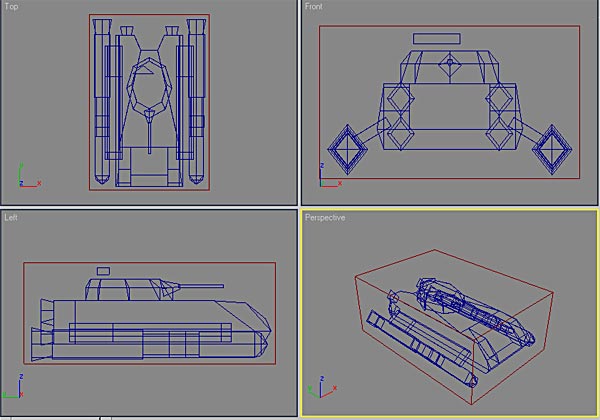
more. Here is an example of the Shadow Mesh compared to the main mesh:
Notice that the Shadow Mesh is even simpler than
Collision Mesh 1. The struts have been removed completely, the indentation
on the front has been removed, and the turret is just a diamond. Remember
that all you're looking for here is a vague silhouette. Any more detail
than this is really not necessary and just slows down the renderer.
Putting It All Together:
So you've made all the pieces and optimized them
as much as humanly possible. So what do you do with them?
Textures:
The only pieces that need texturing are the LOD's.
If you are going to use the auto generate function, then you only have
to texture the one's that you have created. The exporter will take care
of the others. None of the other pieces are visible (except for the
shadow, which gets it's texture from the rendering engine), so it doesn't
matter what textures are on them.
Names:
If you check the "Use Object Names For Export"
box, then the exporter will automatically look for the names and export
each piece accordingly. The way it works is that the exporter looks
for the name, and then ignores everything following the "_".
So if we call this vehicle "RocketTank", the pieces would
be named the following:
lod01_RocketTank
lod02_RocketTank (...and so on if you make additional
LOD's)
col01_RocketTank
col02_RocketTank
bbox_RocketTank
shadow_RocketTank
There is a box labeled with a question mark after
the "Use Object Names For Export" label. If you click on it,
it will give you a list of the names to use. Note that since the exporter
ignores everything after the "_", you can use any names you
want. All that is important is the first part. The rest is just so you
can keep track of what you're exporting. Capitalization makes no difference,
so "LOD01" is the same as "lod01"
The Final Export:
- After you have prepared all of the pieces and
named them, make sure that only the pieces you want to export are visible
( I normally keep each set of objects in it's own scene to avoid confusion)
- Select "Model
Import/Export" from the "Battlefield Tools" menu.
- Check the box next to "Auto Generate LOD's"
and leave it set to 6, even if you have modeled more than 1 LOD. (Only
advanced users would have a reason to change this.)
- Check the box next to "Use Object Names
For Export".
- Check the box next to "BSP Optimization".
(This is another optimization technique that the game engine uses. There
are rare instances where you might turn this off, but it's safest to
leave this on.)
- Check the box next to "Force MatID"
and type in the number you want to use. (This sets 1 material ID for
the entire object. If you have assigned custom ID's to different surfaces
in Max, then leave this unchecked. How to do this is explained in other
tutorials on the site.)
- Make sure all other boxes are unchecked unless
you know what they do. These are advanced options that most people don't
use and can mess up your export.
- Click on "Export", navigate to the
proper "standardMesh" folder, and click "Save".
You've now exported a completely optimized standardMesh
file for Battlefield: 1942. The file format is the same for Battlefield:
Vietnam.
-- End of Tutorial --
|